Interoperability between SE tools (HUBx)
Extended Interoperability: A Methodological Approach
Current needs in the field of Systems Engineering
Systems Engineering is a demanding discipline that aims to orchestrate the activities of many professionals from different disciplines. Many information sources are used, comprising different file formats and tools, often from various vendors, and not designed to provide seamless connectivity. Therefore, most Systems Engineering projects involve many tools, file formats, modeling languages, and other diverse aspects. This poses the challenge of integrating all assets to maintain the digital thread and ensure traceability across the system lifecycle.
This becomes even more challenging when considering our complex organizations and interactions with third-party entities, partners, customers, and suppliers.
Braking silos between tools, repositories, disciplines, lifecycle stages, departments, and even organizations represents a must in any modern systems engineering project. Therefore, a change of mindset is required when it comes to defining the toolchains.
The larger the number of disciplines involved in a digital project, the more complicated it is to design and maintain a digital thread between all of them. The idea of minimizing the number of dependencies by concentrating different information on one single tool has also been demonstrated to be a big problem. The tools required by every discipline need to be very specialized so that the expected features can be offered to the engineers.
Engineers do not need another new tool with more capabilities, but a way to interconnect and interoperate all the existing engineering environments. The different pieces of information forming a complete systems engineering project do not need to be centralized. The information must persist in their repositories, managed by the best possible tool to cope with this particular type of information (ASoT – Authoritative Source of Truth). On top of that, an interoperability layer – the Interoperability HUB – needs to be implemented to connect and synchronize all the different sources (SSoT – Synchronized Source of Truth).
This Interoperability layer, the SSoT, shall provide not only connectivity among the different involved tools, formats, and repositories, but also a series of services:
- Semantic authoring tools to help authors cope with the principle “right the first time”
- Quality inspection for different types of artifacts
- Verification & validation
- Global change control
- Configuration management
- Cost-to-cost traceability, including matrices and impact analysis
- Risk analysis for different sorts of information
- Information and knowledge management
- Several transversal processes, which are understood as Technical Management Processes.
How a SMART interoperability system can help meet these needs
Let us now identify the pillars that might uphold all this infrastructure. According to our approach, there are 6 main pillars:
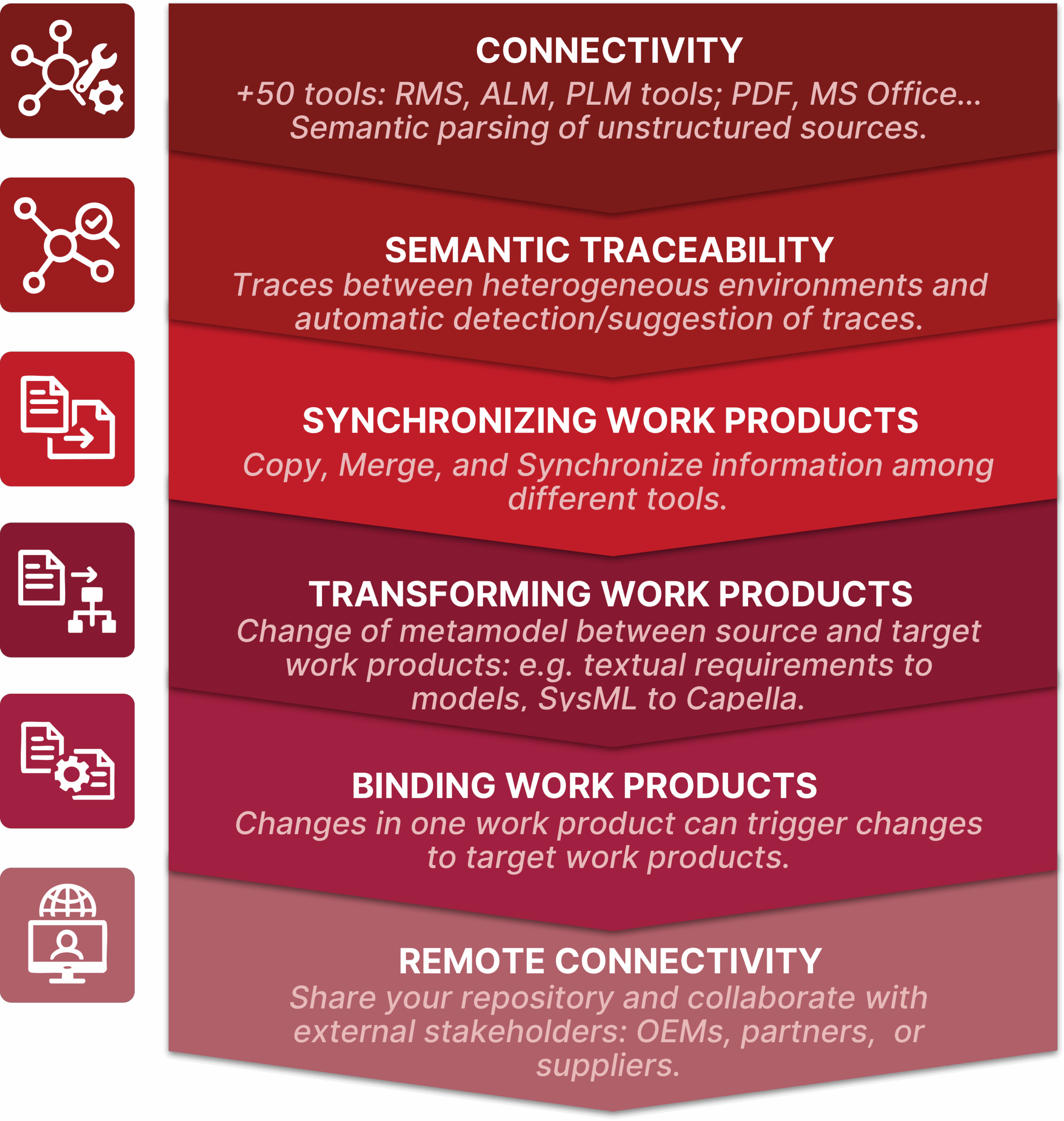
These 6 pillars represent the core of the INTEROPERABILTY Hub promoted by The REUSE Company and aim to offer a passport towards a digital thread without frontiers. Let’s discuss, one by one, all these pillars.
1. Connectivity between system engineering tools
The first pillar of the Interoperability Hub corresponds to the ability of SES ENGINEERING Studio to connect to +50 different tools. From Requirements Management to MBSE tools, through ALM, PLM, MS Office, PDF, and others… The Hub avoids point-to-point connectivity by providing a standard representation of the sources and maintaining an SSoT (Synchronized Sources of Truth).

The Hub represents a canonical representation for artifacts such as requirements, risks, tests, conceptual models, physical models for different disciplines (Mechanics, Thermal, Electronics, Software…), simulation models, etc. This canonical representation must always be in sync with the real source. Therefore, as soon as a document is connected to SES ENGINEERING Studio, a synchronization/reconciliation must always be done. Changes are highlighted, and other operations to deal with changes (as will be presented in the next sections) are offered.
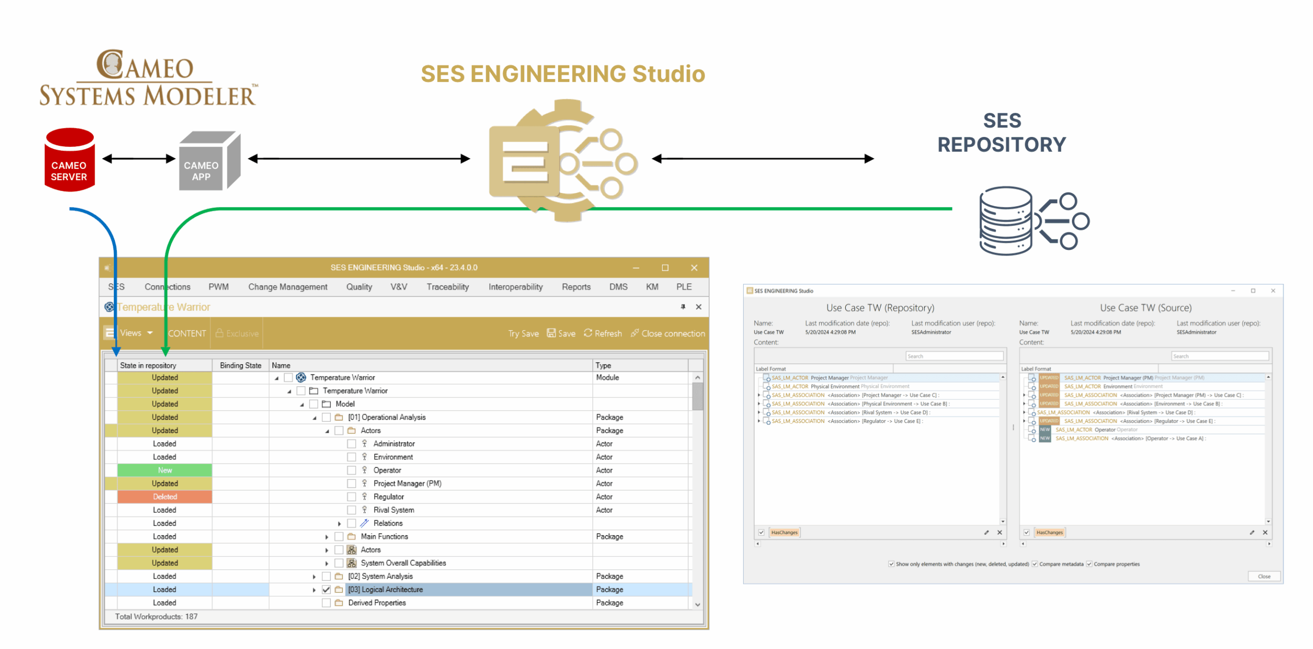
Connecting a tool to the Hub represents the implementation of a bi-directional transformation from the corresponding tool (or file format) into the canonical representation model of the Hub. When possible, this transformation will use the APIs provided by the target tool. The Hub implements mechanisms to promote a quick implementation of the transformation for additional tools. This way, the list can be easily extended when new tools need to be part of the Hub.
2. Semantic Traceability
Starting with the set of connectors to different tools, the Interoperability Hub relies on SES ENGINEERING Studio. SES features a complete traceability module that allows establishing and managing traces among any of the tools and formats that can be connected in the first pillar.
That is, do you receive regulations from a regulatory body in PDF format? The Hub includes semantic modules to provide SMART parsing of unstructured sources. It identifies the meaningful blocks and transforms those blocks into configuration items in the Hub. From this moment on, you can trace a piece of regulation to one of your system-level requirements into a tool such as PTC Codebeamer or another RMS. Then you derive this requirement into a sub-system requirement, connect a model developed in Capella, and trace your requirements to Capella elements. You can generate your test plan into a tool such as V&V Studio, MS Excel, or any other testing tool and trace your tests to your requirements. All these traces can be created with the click of a button, connecting to the real source of each item, and keeping the traces in the ontology that forms the core of the Interoperability Hub.
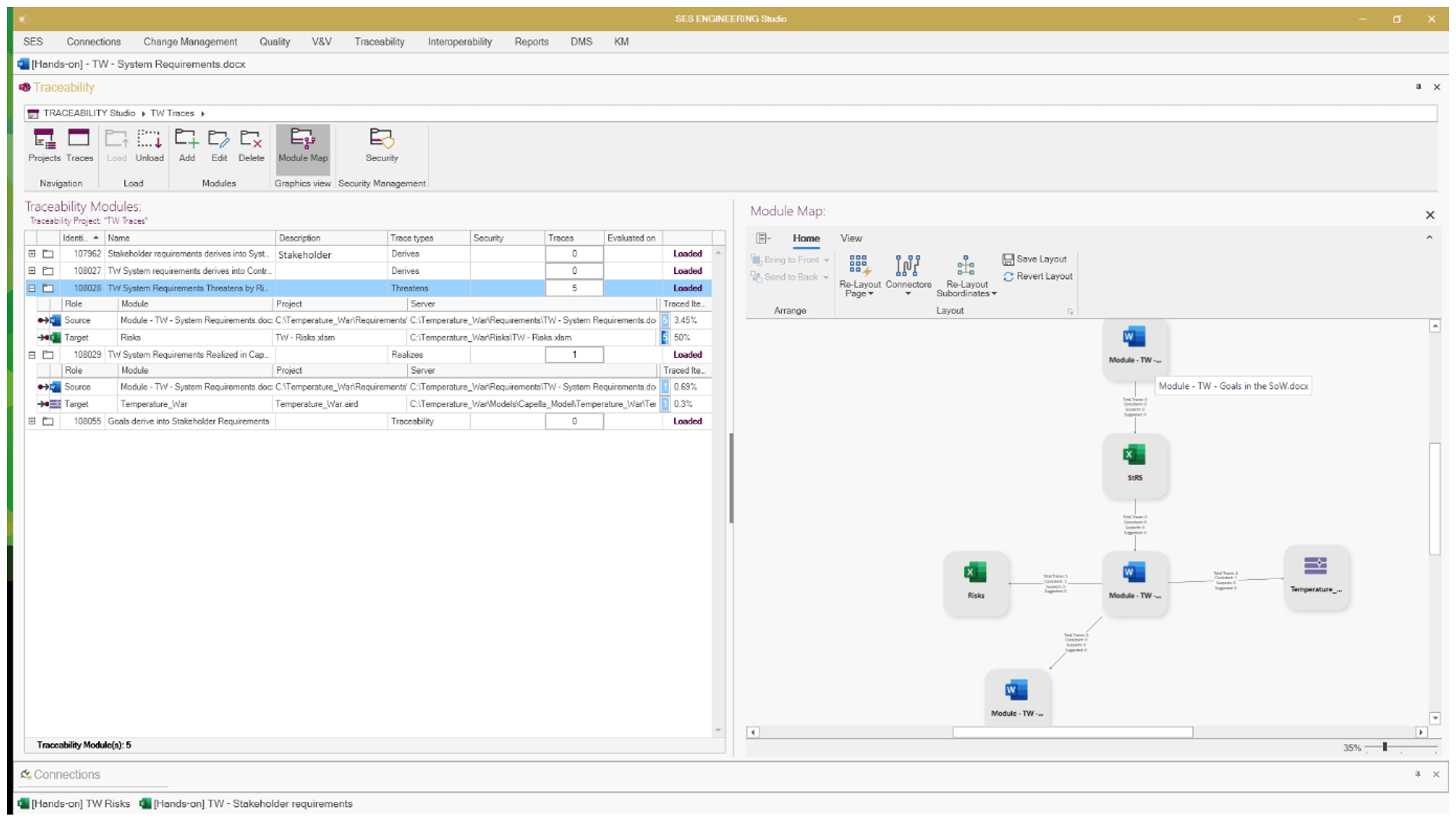
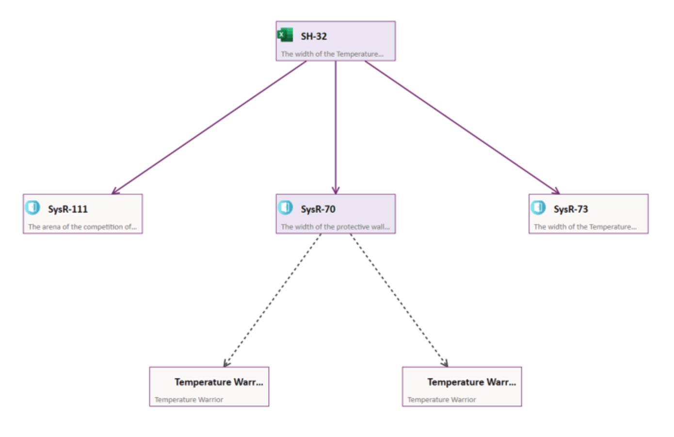
Changes that are inevitable and will sooner or later pop up will alert you about the suspicious links generated in the Hub. Therefore, the traceability capability of the Interoperability Hub and SES ENGINEERING Studio features a graphical representation of the change impact.
This traceability capability not only offers the possibility to create traces among multiple tools and repositories. It also offers the typical impact analysis, traceability matrices, etc. Furthermore, this tool has been designed on top of a semantic ontology and embraces different artificial intelligence methods capable of suggesting new traces, thus easing the required but demanding traceability activities.
3. Synchronization of sources
Traces created among different sources minimize the need for making copies of a set of artifacts in a tool, to be copied into another tool (most of the types only with the purpose of establishing traces).
Anyhow, there are still multiple scenarios that require information in a tool to be somehow transferred (copied, appended, synchronized) to other tools.
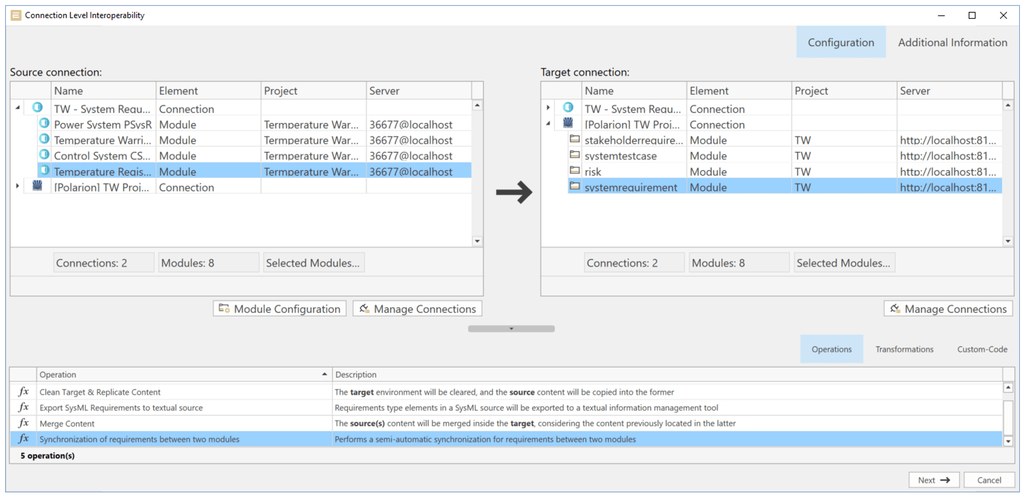
An example of this synchronization of information is found when two different partners are collaborating on the same project. Consider now that the first partner is using a tool like Capella to do conceptual modelling, but the other partner is using any other tool. With the synchronization capability of the Interoperability Hub, information in a modelling tool can be easily transformed into a different modelling tool. When both partners contribute to the same model, the Hub implements a sync mechanism to reconcile all these changes. Thus, allowing for closing the change/Sync loop as many times as needed.
The mapping between source and target is fully customizable. Along with the items themselves, one or more attributes in the source can be synchronized with the target. Also, the Hub allows filtering synchronized elements by attributes, types of objects, stereotypes, the location of the item within a specific package, or even the presence in a specific type of diagram. This way, the elements that match the filter in the source can be transformed into a specific element in the target. Other similar objects from the source that do not match the filter could be transformed differently. This represents an answer to the flexibility that real-life documentation (mainly models) normally requires.
Another interesting example could be the implementation of the so-called Zig-Zag model. In this model, some engineers prefer to develop requirements in a Requirements Management System, even though the Interoperability Hub allows traces between different tools. The requirements are then transferred into a modeling tool where the logical architecture is defined. In the MBSE tool, requirements (the “copy” from the real requirements, still in the RMS) are traced to model elements (components, functions, states/modes…). This architectural definition might create the need for additional requirements derived from the architectural decisions, as well as some other changes to existing requirements. Once the first layer of architecture is finished, including the trace between requirements and models, the Interoperability Hub can take a delta of the requirements document, together with the traces, and reconcile this delta with the real source of truth of the requirements, still in the RMS.
As recursiveness is applied to continue with the different layers of decomposition of the system, this process of exchange and synchronization between requirements and models is executed repeatedly. This is the source of the name zig-zag model.
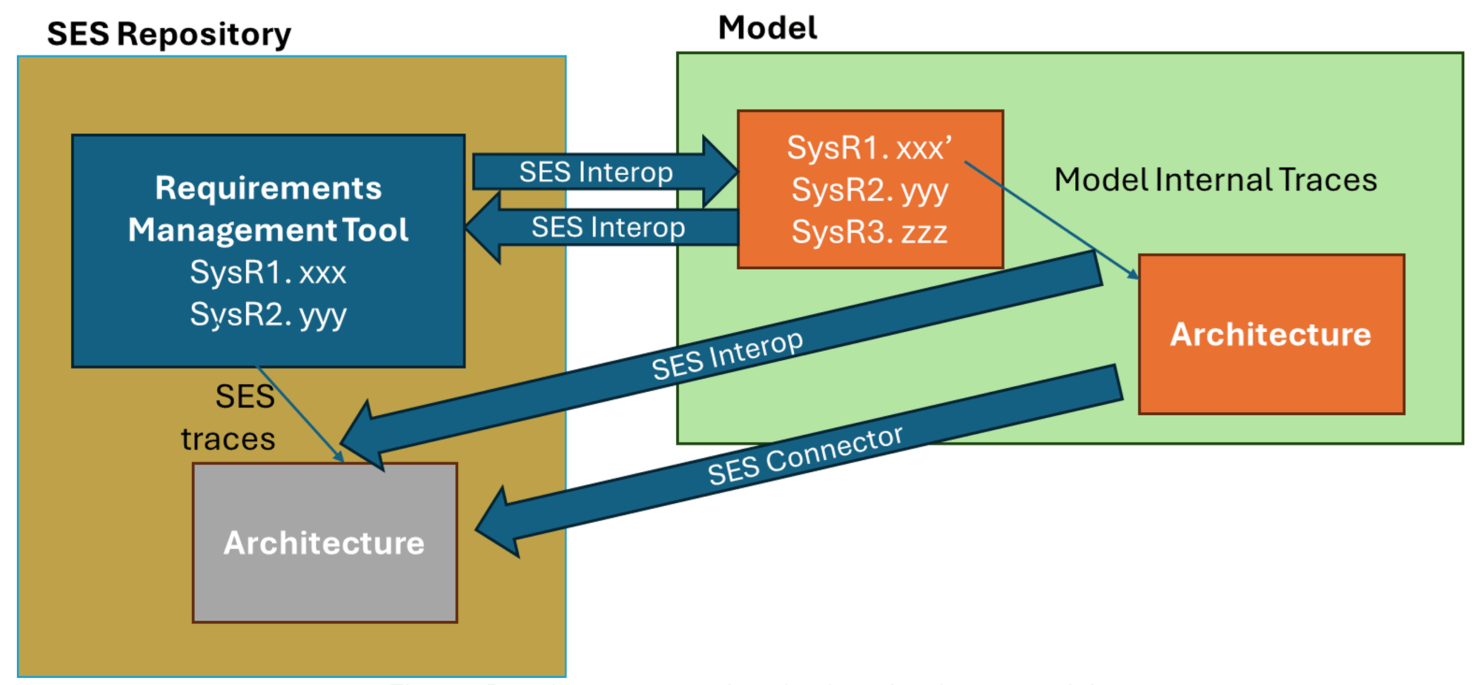
4. Transformation of work products
In the cases described above, no further semantic transformation is needed. The metamodel of the requirements in the source, the RMS, remains the same in the target, the MBSE tool. The same applies to the MBSE transformation described at the beginning of the previous section.
However, this doesn’t have to be the same always. The Interoperability Hub also takes advantage of a semantic engine, empowered by an ontology, to deal with more sophisticated transformations. An example of this could be the transformation between Capella models and another SysML-based MBSE tool. Since Capella is not using the SysML language, transforming a Capella model into another SysML model requires a semantic transformation. The Interoperability Hub implements, out of the box, all the typical transformations defined by the Arcadia method. It also provides the possibility of more precise transformations.
Another example of transformation implemented in the Hub is the generation of textual requirements starting with a model. In the figure below, a state chart is transformed from an MBSE tool into a textual specification into a requirements management system.
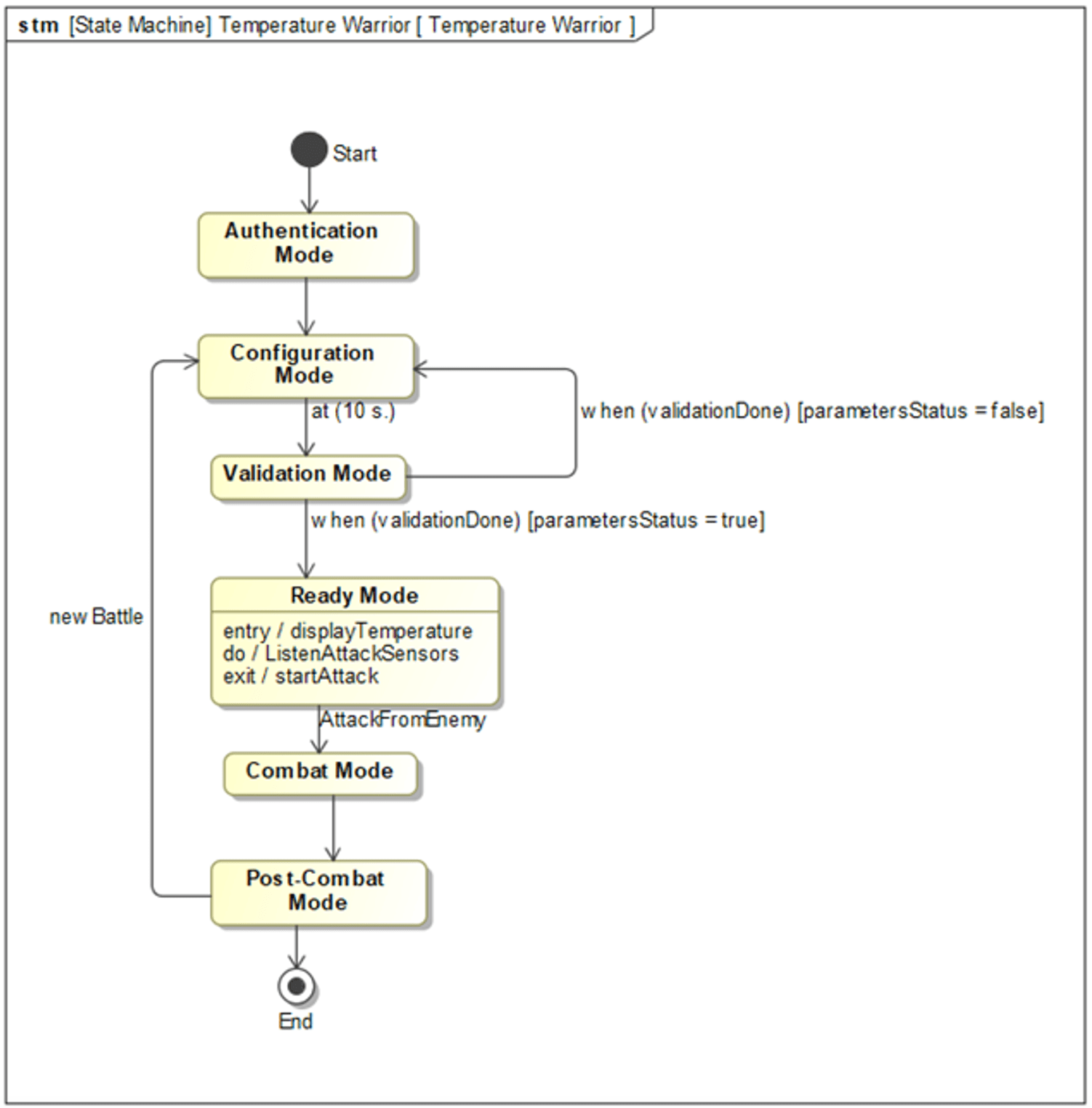
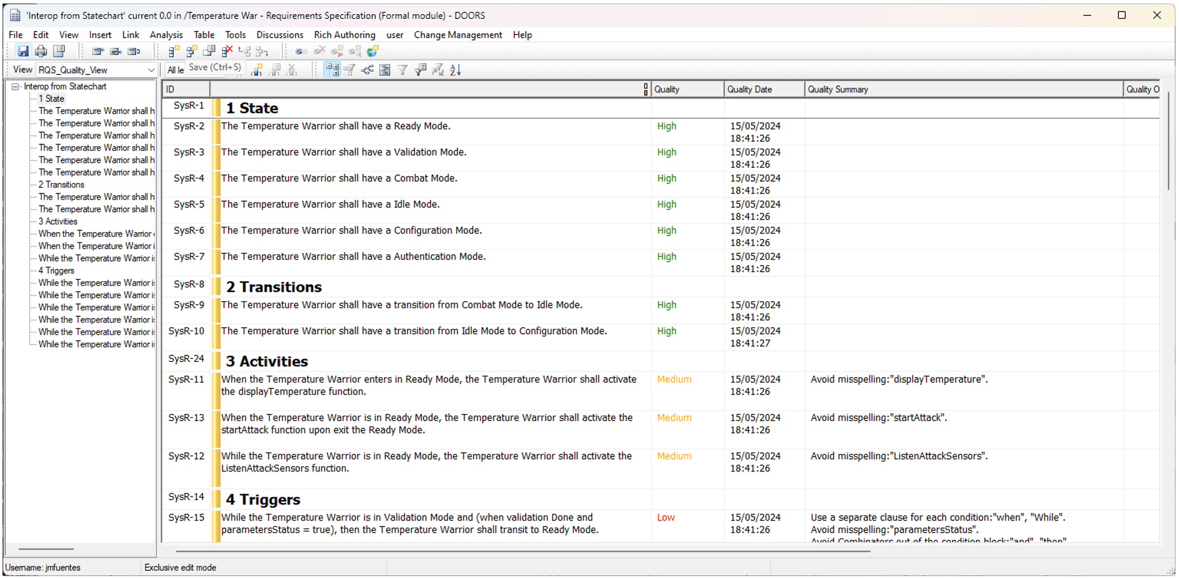
The opposite transformation, where models are generated automatically from a textual specification in an RMS, is also possible with the Interoperability Hub.
Other transformations are also possible. Some examples:
- Automatic rewriting of requirements to meet the rules in the INCOSE Guide to Writing Requirements
- Generation of test cases from textual requirements
- Extraction of controlled vocabulary from a textual specification
- Translation of Requirements between different languages
5. Binding work products
Semantic binding represents one more step in combination with the semantic traceability or the transformations (that also implicitly generate a trace relationship between the source and the target element). A binding represents the possibility to propagate changes when a linked element is changed.
Let’s focus on a simple yet powerful example. We generate a traceability module between a requirements document and a model. Within this module, either manually or semantically/automatically, a requirement is traced/bound to a model element. If the architect modifies the name of the element in the model, the tool will show the impact of this change. That is, which elements are affected because they are connected through traces to the modified element? Once the architect agrees to the change, he or she will have the possibility to propagate this change in the name of the element. That is, all the textual requirements, even in a different tool (an RMS), shall be modified according to the change in the name of the model element.
6. Proxy – remote connectivity
This represents the final pillar of the Interoperability Hub. However, being the last one does not mean that it is less important. All the bindings, traces, transformations, etc. mentioned in the previous pillars are not easy without a semantic tool. However, life is normally even more complicated than this when the tools to be connected are in different infrastructures.
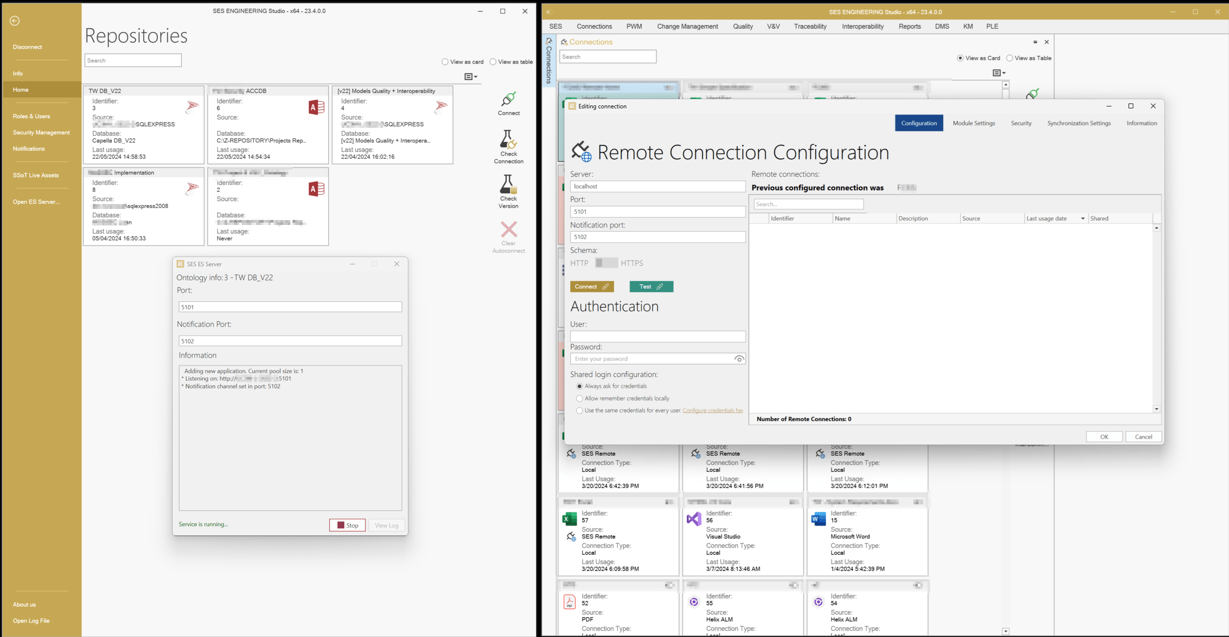
Let’s assume a company has a complete set of tools suitable for different disciplines. Another division within the same company has decided to implement a slightly different set of tools. The synchronization and transformation operations defined above shall require the interconnection of different networks and IT infrastructures. This is why the Proxy layer of the Interoperability Hub allows synchronizations and transformations where one of the ends acts as a Server, and opens the possibility for granted users of the Client side to connect and operate.
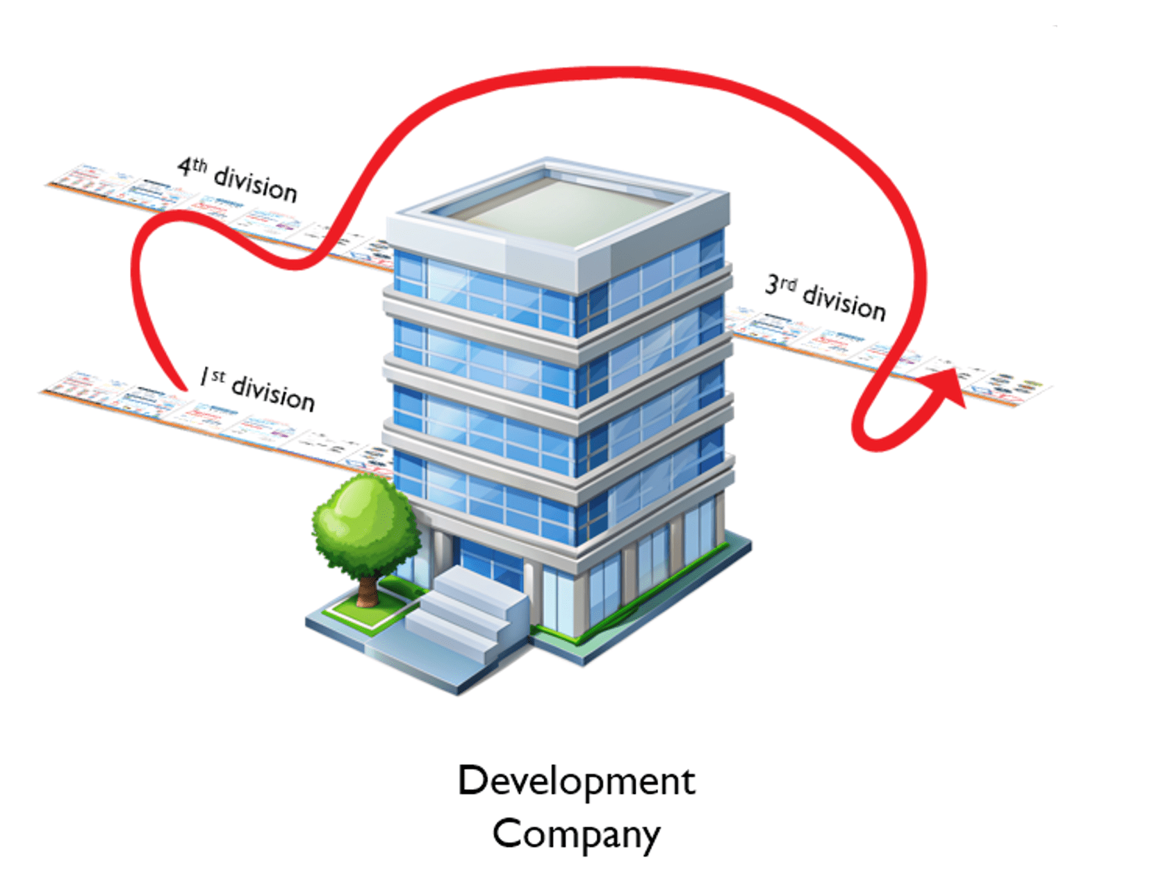
And this could be even more complicated. What if interoperability operations are required between two different partners working on the same project? Or between a customer (let’s say, an OEM) and providers (the tier-1 companies)?
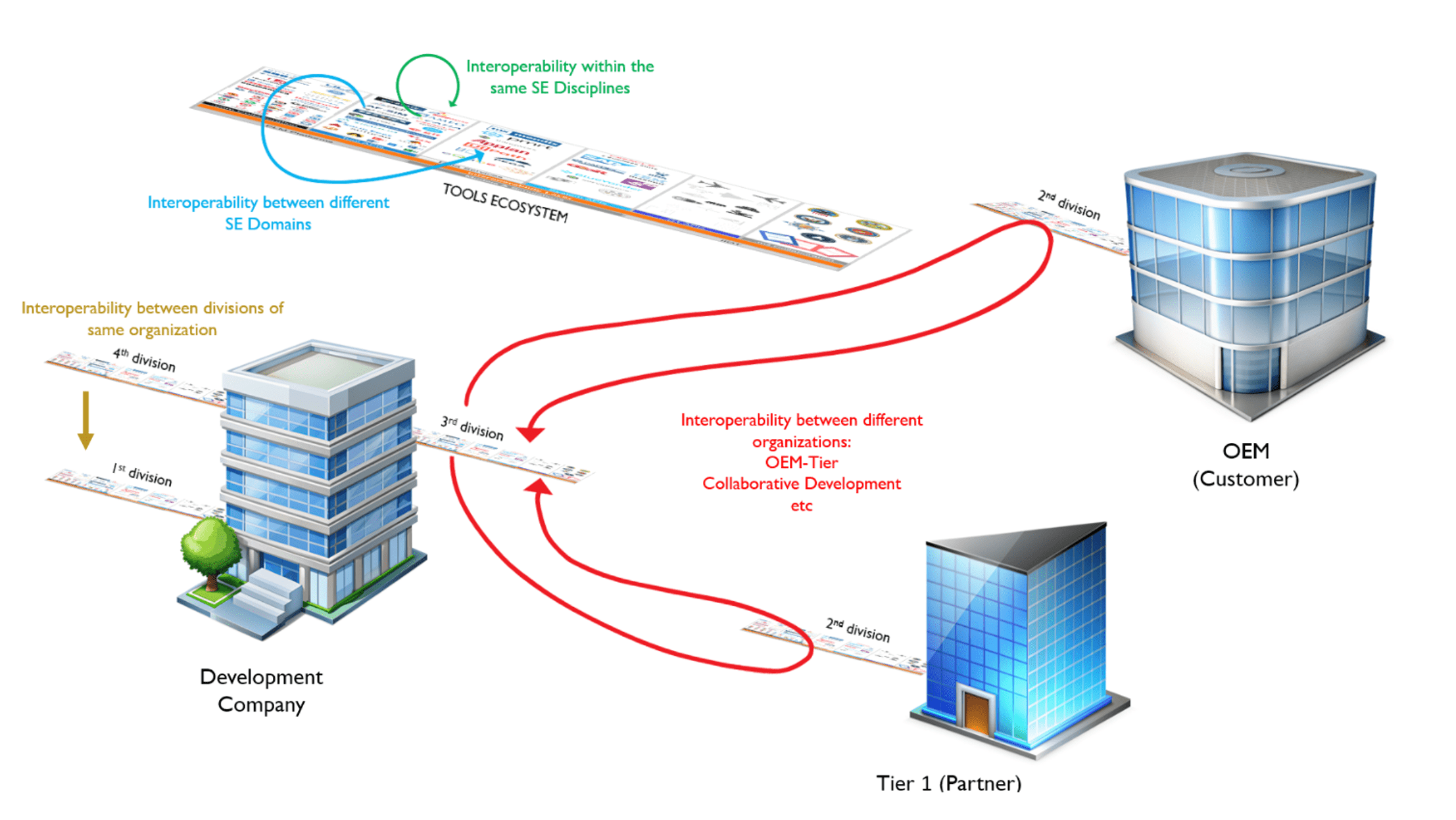
SES ENGINEERING Studio acts as a Proxy (the server side) and allows remote connections on the client side. This allows synchronization of local documents with remote documents to promote concurrent editing of documents across different departments or organizations.
Even the technological boundaries between companies are not a problem for the Interoperability Hub, which allows a Passport towards a Digital Thread without boundaries.
A passport towards a Digital Thread without boundaries: need for TMPs
This approach requires some additional layers before it can be considered as a complete Digital Thread enabler.
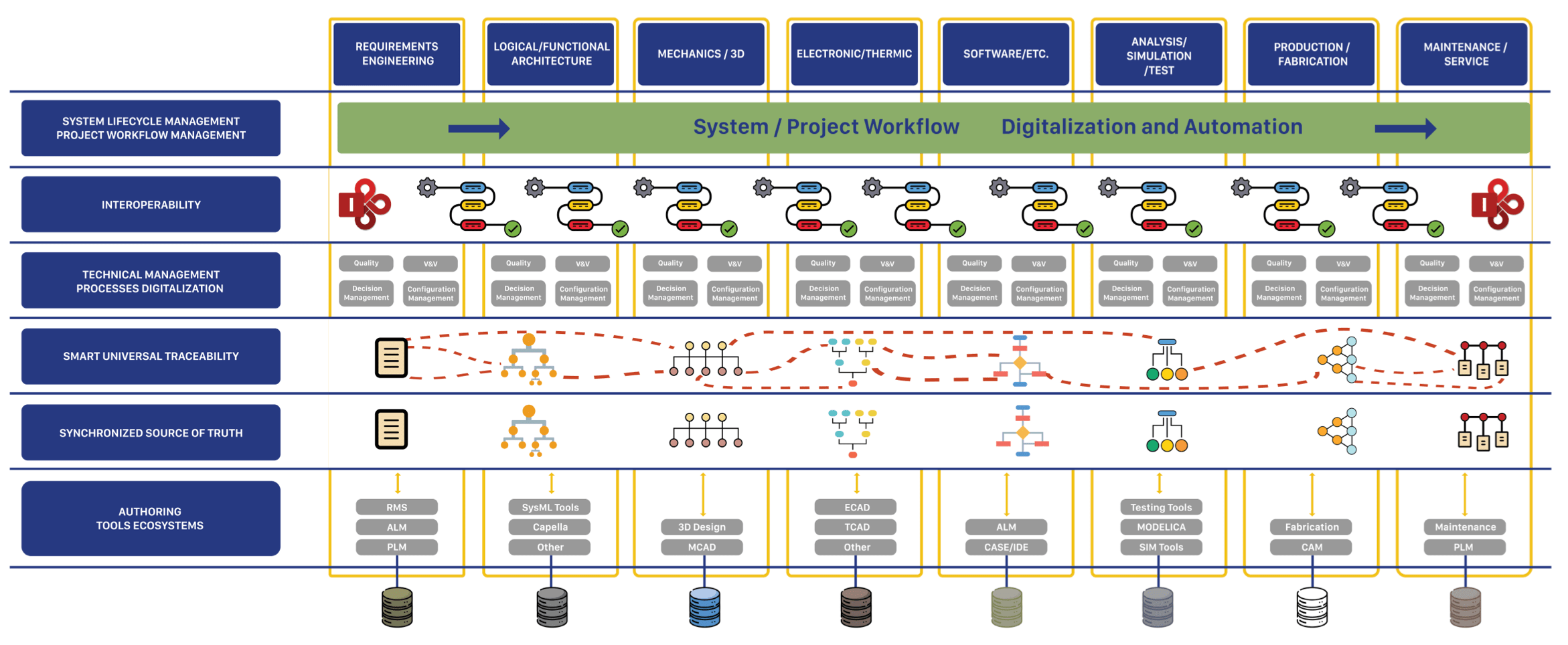
As mentioned above, a series of Technical Management Processes enrich the operations with the Interoperability Hub itself, with different tools forming the tool ecosystem. Some of the enriching TMPs are the following:
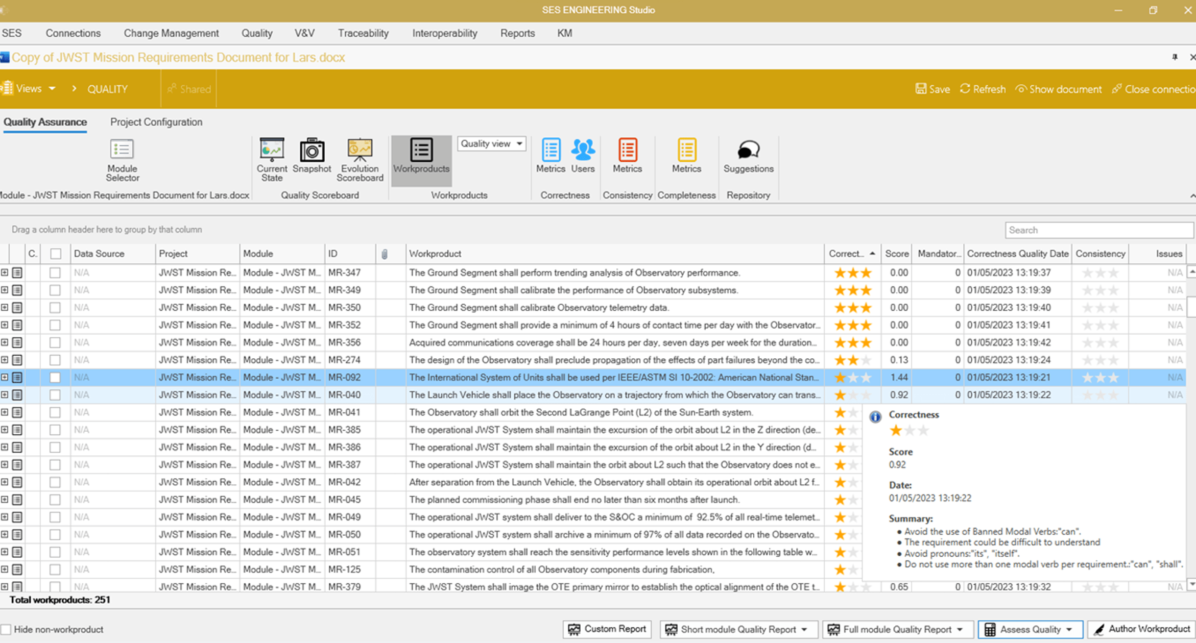
Quality Inspection
Every work product generated along the lifecycle shall conform to a set of drafting rules agreed upon between the quality department and the engineering departments. This being a must for every item, it is even more important when those items are to be shared across different departments or different organizations.
SES ENGINEERING Studio includes a module called QUALITY Studio. This module allows the definition of checking rules for requirements, logical models, physical models, etc. Starting with rules stated in well-known standards and guidelines (INCOSE, ISO, ECSS, NASA…), the tool allows a complete tailoring of the rules, and the agreement of different of rules for the different documents if necessary.
Thus, prior to any exchange, the Interoperability Hub methodology reinforces the idea of checking that every artifact meets with the agreed drafting recommendations.
More information about RQA – QUALITY Studio
SMART Authoring Assistants
Considering the importance of adherence to drafting standards, the sooner this can be checked, the better. That is why SES ENGINEERING Studio also includes an add-in, not to inspect a document once it is baselined, but from the very first writing of the document.
This is the notion behind the RAT – AUTHORING Tool. RAT assists users in real-time, with established rules and requirements patterns (aka boilerplates) in combination with the controlled vocabulary coming from the domain ontology, a model, or both.
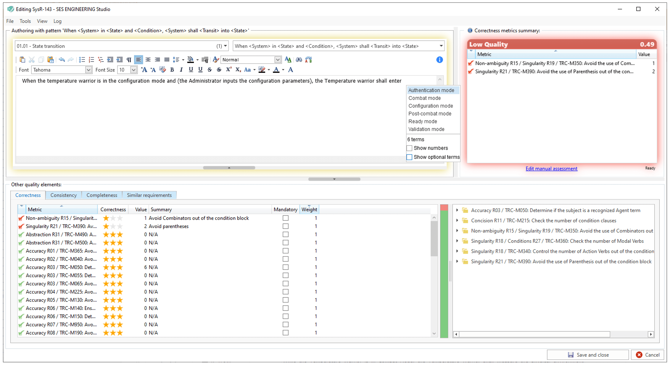
This SMART Authoring Assistant not only helps authors in the demanding activity of creating requirements or architectures, but also minimizes the time required for both formal and informal inspections.
More information about RAT – AUTHORING Tool
Verification and Validation
Once a work product has been produced with the help of a SMART Authoring Assistant and the quality control team has determined automatically whether it conforms with the minimum set of quality characteristics, a more manual V&V process shall be performed.
This process is fully implemented in the V&V Studio module of SES ENGINEERING Studio, and covers the typical stages required to capture and manage evidence, such as:
- Prepare for inspection
- Perform inspections
- Report inspection evidence
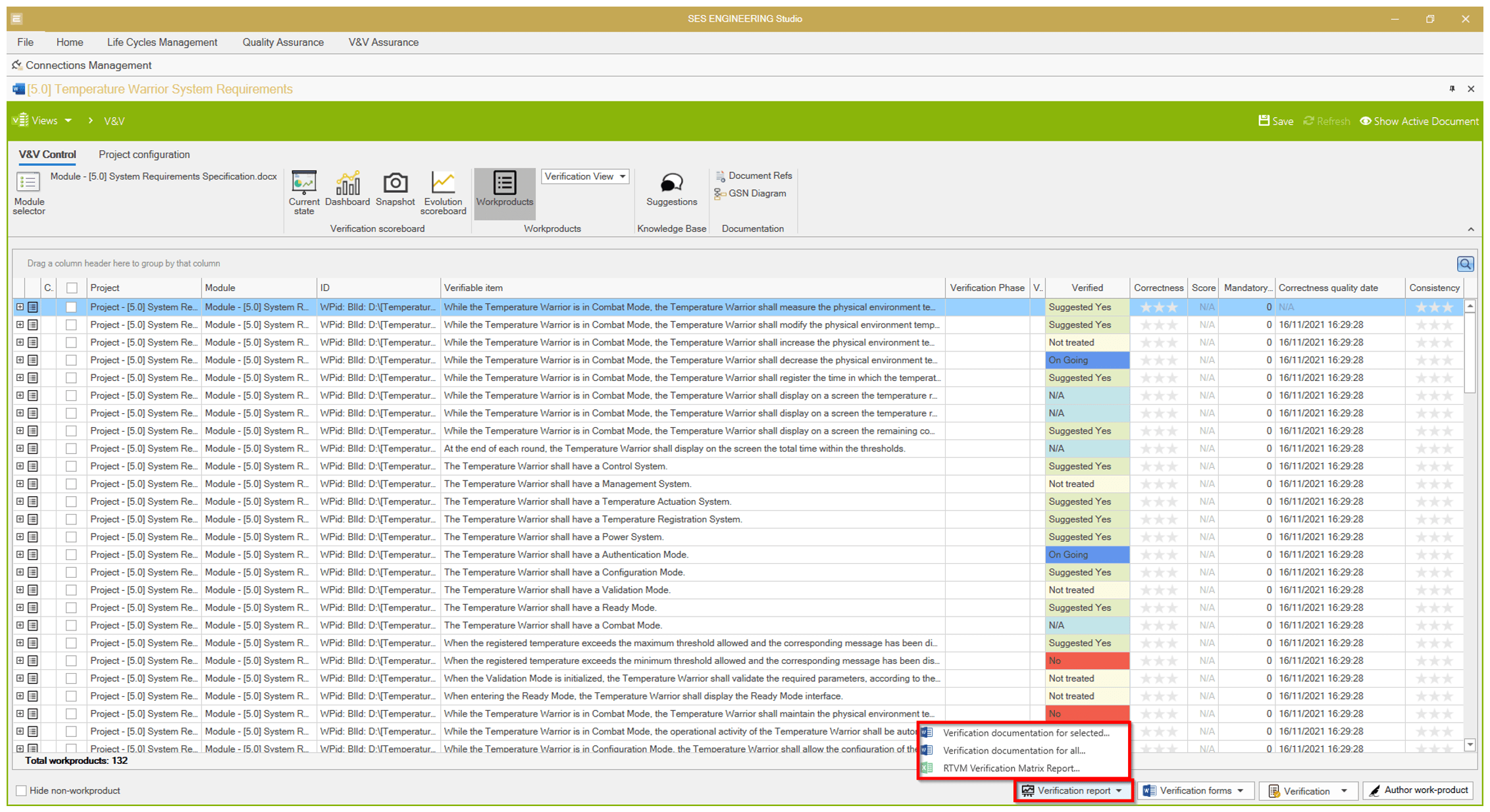
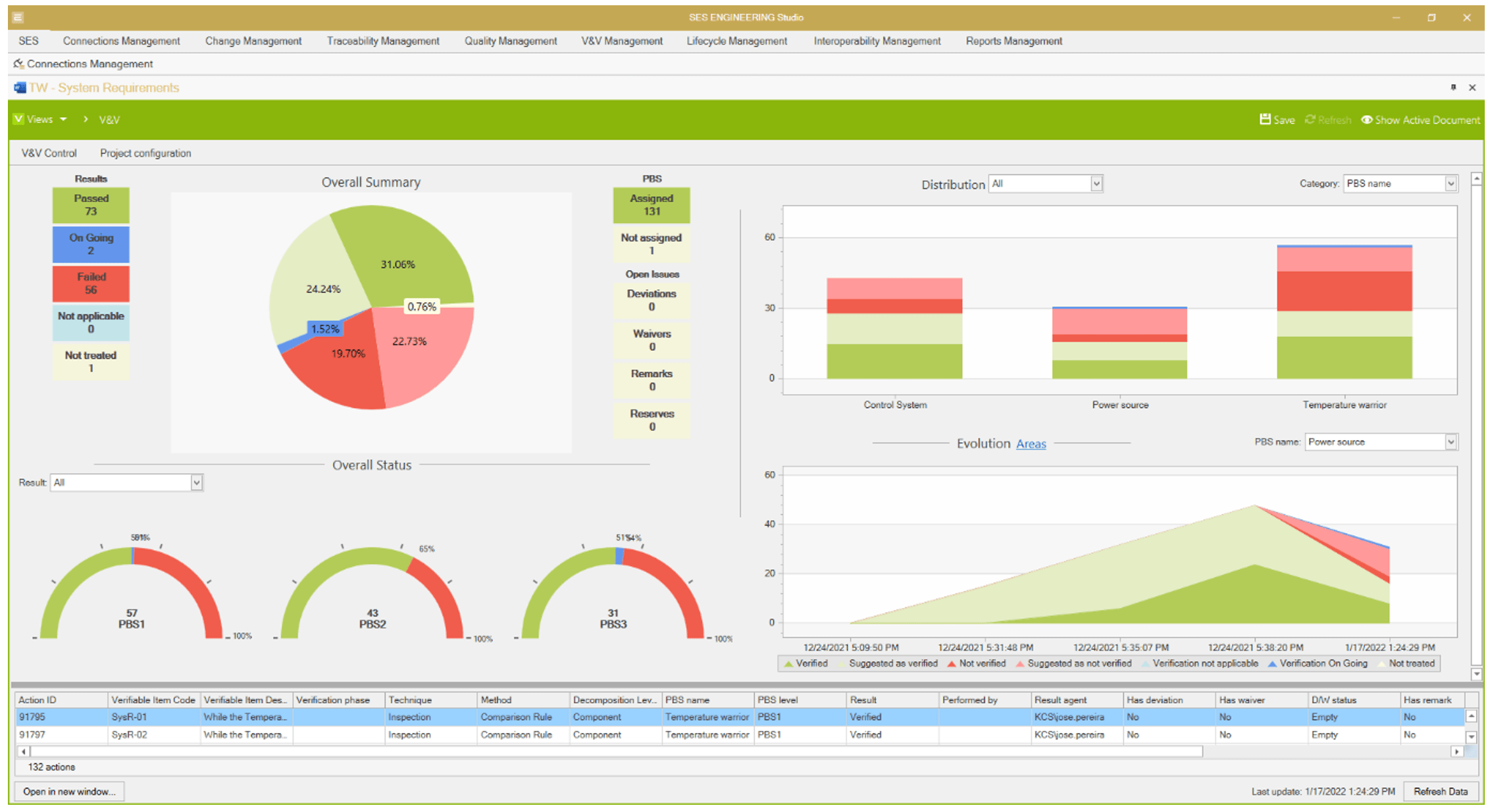
More information about the V&V Studio:
Decision Management
When all the information of a project is connected within the same Interoperability Hub, the possibilities to include Artificial Intelligence algorithms with different purposes grow exponentially.
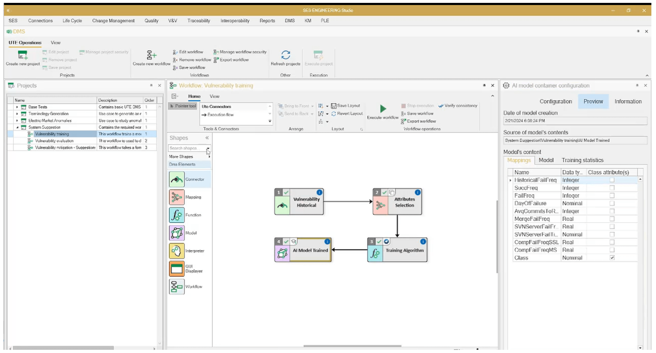
SES INGENEERING Studio includes a Decision Management module that represents a workbench including many well-known AI methods. Those methods can be combined into workflows that permit pipeline operations such as data collection, introduction of additional parameters, execution of one or more pipelined algorithms, and preparation of reports, including the evidence used to obtain such conclusions.
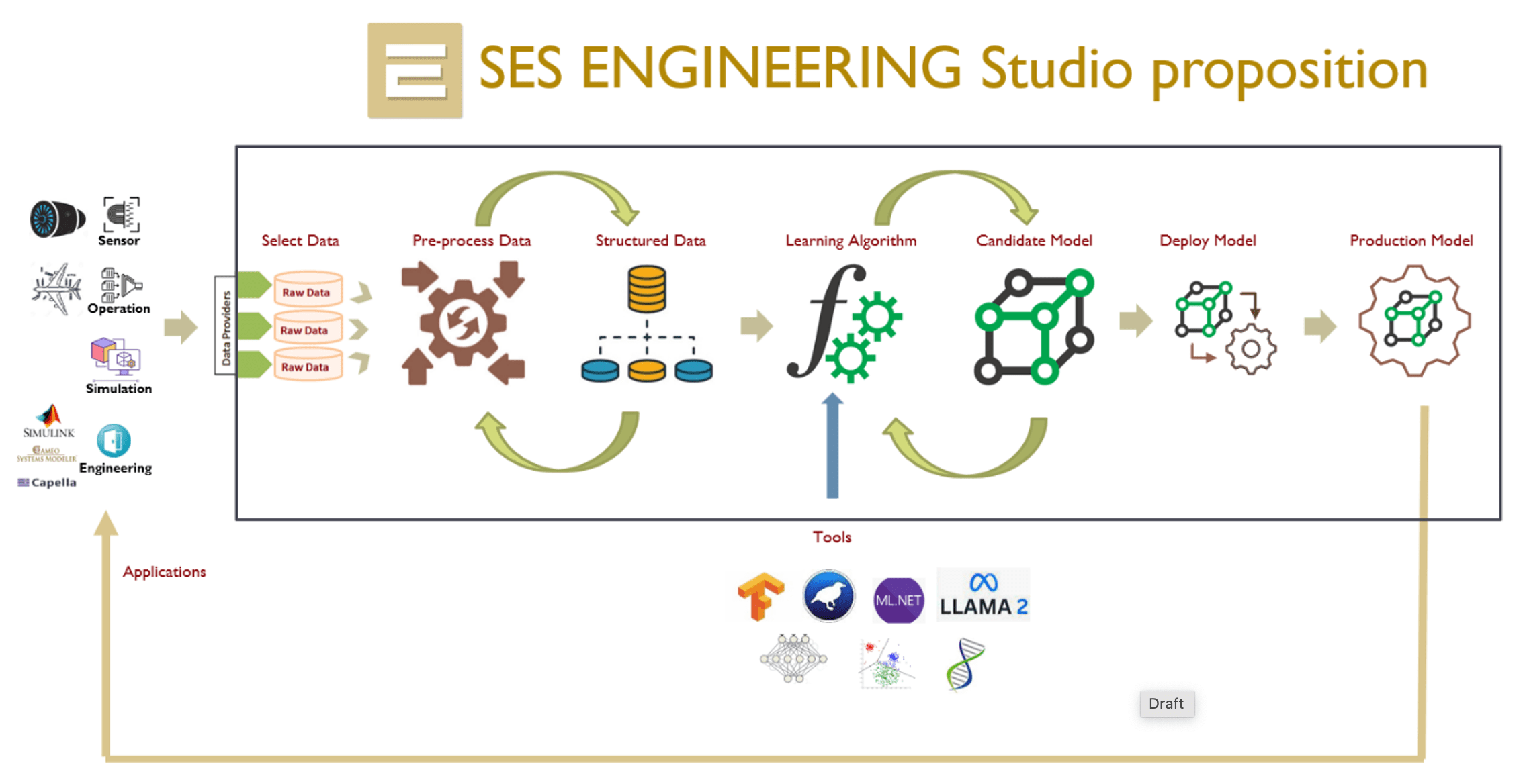
Examples of operations with the DMS module of SES ENGINEERING Studio are:
- The automatic extraction of a domain-specific vocabulary starting with a set of textual requirements
- The classification of requirements according to multiple criteria
- The identification of mismatching information in a project
- The trade-off analysis of different architectural decisions
Configuration Management
Configuration Management is a must in every project. That is why most of the tools already used by engineering companies provide that capability. However, there might be two possible problems with these tools:
- When engineers use non-engineering-oriented tools or file formats such as MS Office or PDF
- Configuration management is represented as a whole, for a complete project, and not as a document-oriented or tool-oriented concept
SES ENGINEERING Studio offers Configuration Management capabilities at two levels: for the sources connected to the Hub, and also a global configuration for the entire project.
More information about Configuration Management, a capability within SES ENGINEERING Studio
Information Management
Every piece of information exchanged in the Interoperability Hub is subject to being retrieved and reused. Once a work product has been successfully inspected to demonstrate that it meets the drafting rules attached to it, it will be semantically indexed and stored in the semantic search engine of the Interoperability Hub. This will enable authorized individuals to query the system and obtain work products relevant to the query.
Transferring the retrieved item into a new project involves a series of steps:
- Verifying whether this item also conforms to the quality rules agreed for the target project
- Selecting which pieces of the retrieved element are to be transferred
- Following traceability links to try to discover other items also valuable for the target project
Digitalizing the Project Workflow
SES ENGINEERING Studio offers the possibility to manage the flow of all the different activities in a project.
Each activity is defined in the tool. Every input and output for a given activity is represented by one connector in the Interoperability Hub. In this way, all the activities shall be under control and enriched with all the Technical Management Processes mentioned above.

